Automatic Solar Generation Limiter (ASGL)
Automatic system for limiting the generation of SPPs included in the country’s energy system
Description of the object of regulation
1.1. General characteristics of the object of regulation
We bring to your attention a description of the hardware and software complex, which in automatic mode allows limiting the generation of SES according to the specified setting, which is necessary to optimize the values of flows in high-voltage lines in the event of a possible uncontrolled increase in generation during the day.
The object of automation was a pool of 11 SPPs with a total possible generated capacity of up to 300 MW, operating as part of the unified energy system of Ukraine.
Each of the SES is a complex consisting of modules of solar photovoltaic panels (SEP) placed on the field, which are connected in groups to inverter stations (IR), which convert the panels’ constant voltage of 400 V into an alternating voltage of 10 kV.
Next, electricity is supplied to the 110/10 kV substation via high-voltage lines of 10 kV, from which it is, in turn, supplied to the electrical networks of the substations of the power system.
The process of collecting and converting electricity is fully automated.
The complex includes an operational and informational subsystem that provides visual control on monitors of dispatchers over all work processes of SES.
It should be emphasized that there is no comprehensive remote adjustment of their operating parameters at the level of electrical panels and inverter stations
The entire set of equipment was delivered and commissioned by AEG (Germany).
1.2 Basic principles of SES construction
As it was said above, these SES consist, in fact, of a complex that generates electricity (FEP, IW) and a power boosting substation of 110/10 kV.
The task was to create an automatic system for limiting the generated power at the IC level.
The generating complex of each SES includes from 20 to 27 IUs of the same type, each of which includes two inverters with an output power of 630 kVA (several IUs also have inverters with a capacity of up to 250 kW), operating on one power transformer. which increases the output voltage to 10 kV.
A pair of IC inverters operates in the «master-known» mode and is controlled by microprocessor nodes of the inverters. This mode is characterized by the fact that at low FEP illumination, they are served only by the leading inverter, and when the input power increases by more than 20%, the slave is automatically connected and the FEP group is divided in half in the part of the connection to the inverters. When the output power drops below 20%, the slave inverter is turned off, and the master serves all FEPs again. This mode makes it possible to increase the efficiency of the IR during the period of weak FEP illumination (morning, evening, cloudy).
An industrial controller is installed in each of the ICs, which ensures the collection of technological information from each of the inverters, from all FES, the power supply system for own needs and weather data.
Collected data are transmitted to the server of the operational information complex located outside Ukraine via the local computing network, which connects all ICs in a ring using a fiber-optic communication line and through a router via a VPN channel.
In this way, technological information about the work processes at the SES is collected and processed by appropriate programs and displayed in real time in a form convenient for the operator on the monitors of the workstations of dispatchers on duty both at the level of the SES and at the level of the central dispatch center (CDP).
In this case, the workstations are «clients» of the server, which provides them with information from the VPN channel.
A separate function of the IP control controller is the possibility of individual control of each of the inverters in «manual» mode either from the remote control on the IP or from the workstation on the CDP.
Description of the composition and functioning of the automatic generation limitation system (ASOG) of the SPP
2.1. The following basic conditions were included in the technical requirements for creation:
— work in automatic mode in different periods of daylight (morning, afternoon, evening);
— The possibility of local «manual» adjustment in case of communication breakdown with the upper level of automatic control;
— human-computer dialog interface
— not violating the existing regime of operational control over the operation of the equipment.
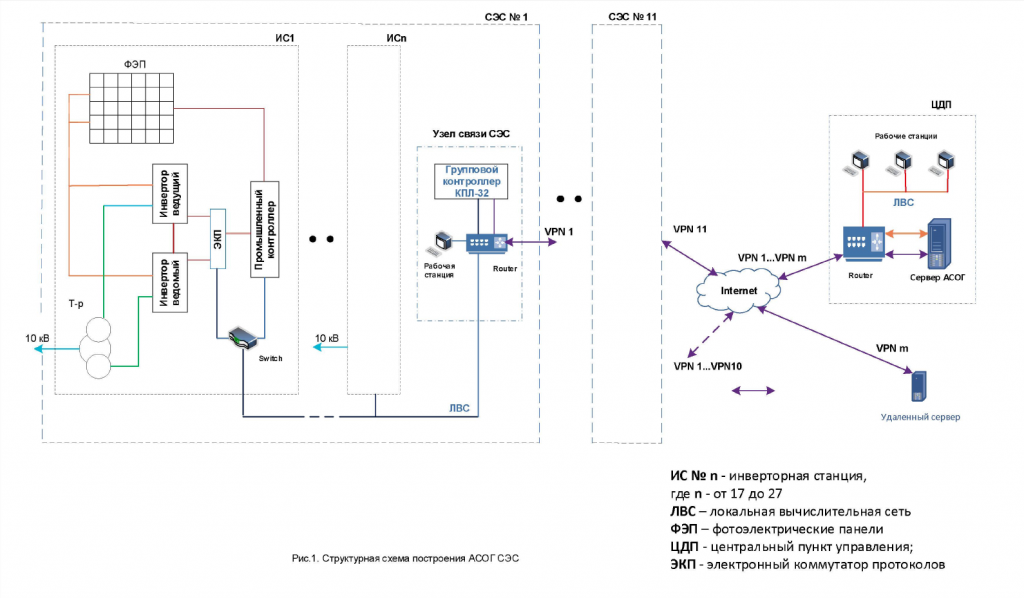
2.2. To solve the tasks, a specialized hardware and software complex with the following architecture was created (see Fig. 1).
An Electronic Protocol Switch (EPS) is installed in each IC between the inverters and the industrial controller, which supports independent exchange of data between the inverters, forms a clipboard through which exchange with the existing industrial controller is ensured, and additionally through the Ethernet port of the existing computer network with the SES group controller.
The SES group controller is installed in the SES communication node and supports data exchange over the network with all ECPs of the SES of the internal local network through the first Ethernet port.
Second Ethernet port. serves to exchange data through a VPN channel with a server installed in the Central Government.
The server maintains communication with all SES group controllers from separate VPN channels.
The components of the complex have the following technical characteristics:
— EKP is a specialized controller based on an STM-32 microcontroller with built-in application software running on the platform of the Free RT OS operating system;
— KPL32 SES group controller (programmable logical KPL-32 controller of our own development) — a module based on an ICOP type industrial controller with a pre-installed Linux operating system, on which platform the built-in application software functions;
— OIK D2 a server with a pre-installed Windows 10 operating system, on which the licensed application software «OIK D2» is installed;
— Workstations are «clients» of the server.
All the listed components of the complex for information communication use the resources of the existing computer network.
2.2. The created ASOG supports the following mode of operation.
All ECPs poll the inverter in a continuous cycle, form a buffer of received data and issue information upon request (Modbus RTU protocol) to the industrial controller of the active operational control system, and in the status of the server of the internal computer network (IEC60870-5-104 protocol) to the SES group controller. In the reverse direction, the control commands of the inverters are received from the EKP group controller. In this way, a «transparent» mode is supported for the operation of the existing control system for receiving data from inverters and the operation of the generation limitation system, which is created in real time.
The SES group controller transmits data to the CDP server in real time via a VPN channel in the IEC60870-5-104 protocol.
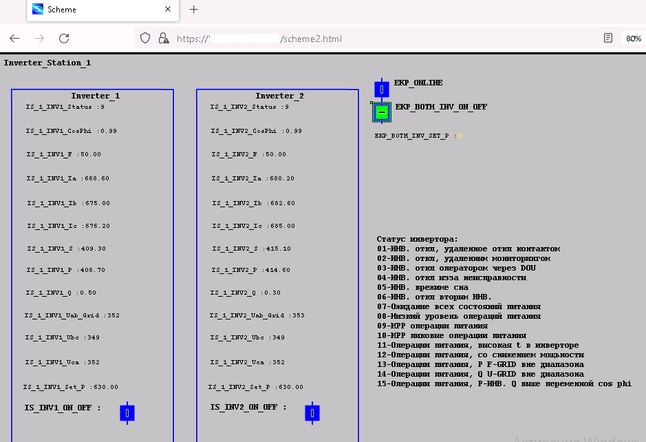
At the same time, thanks to the Web-interface built into the controller on the monitor connected to the technological computer, it is possible to observe the state of all inverters connected to the SES and control them in «manual» mode by the staff on duty of the SES.
This function is used in the event of a disruption of the information connection between the group controller and the CDP server and allows you to locally control the inverters from the workplace of the SES on duty using commands by phone from the CDP dispatcher.
In normal mode, information from all SES group controllers is sent to the CDP server via separate VPN channels. On the server, autonomous tasks for processing the received parameters from each of the SES are launched and, in accordance with the given algorithm, the data from the inverters are processed, taking into account their current state, including the values of the levels of their individual set load.
Individual settings of inverters are calculated, based on the set value of the maximum possible power generation of the SPP, which is set by the dispatcher of the CDP on request from the dispatcher of the regional power system.
These values, as analog remote control commands, are issued by each of the tasks to its group controller, which, in turn, transmits to the inverters connected to it. The maximum time spent on the process of setting the set value of the generated power does not exceed 2 minutes per SES.
Further, the task analyzes the received current power values and, if necessary, adjusts the individual settings of the inverters, achieving a deviation from the overall set value of only 2%.
The processing algorithm takes into account the state of the inverters at different times of the day and their «master-known» mode of operation, as well as their possible off-duty shutdown.
It is clear that with a drop in solar activity, the system cannot increase the generation value in any way.
An additional function of ASGL is the transmission to the system operator of the regional power system of the current values of the power generated by the inverters of reference ICs and the levels of solar activity measured by pyranometers installed on them.
The described ASGL is currently in experimental operation, and we have not received any comments regarding its operation.
The application of this type of ASGL is mainly in companies where there are several SES under the central dispatching control, because its architecture involves the use of a single software control complex, which leads to centralized control and management and saves money on the purchase of software, because otherwise, it is necessary to install such complexes at each of the SES.
Addition.
Structural diagram of construction of ASGL
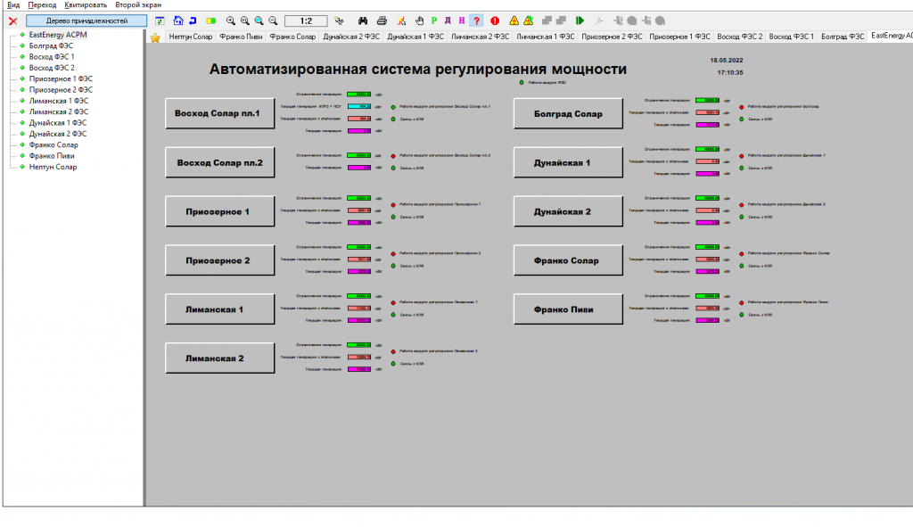
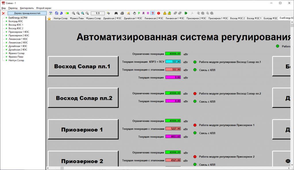
Screenshots No. 1, 2 of the control and management windows on the monitor of the dispatcher’s workstation at the CDP
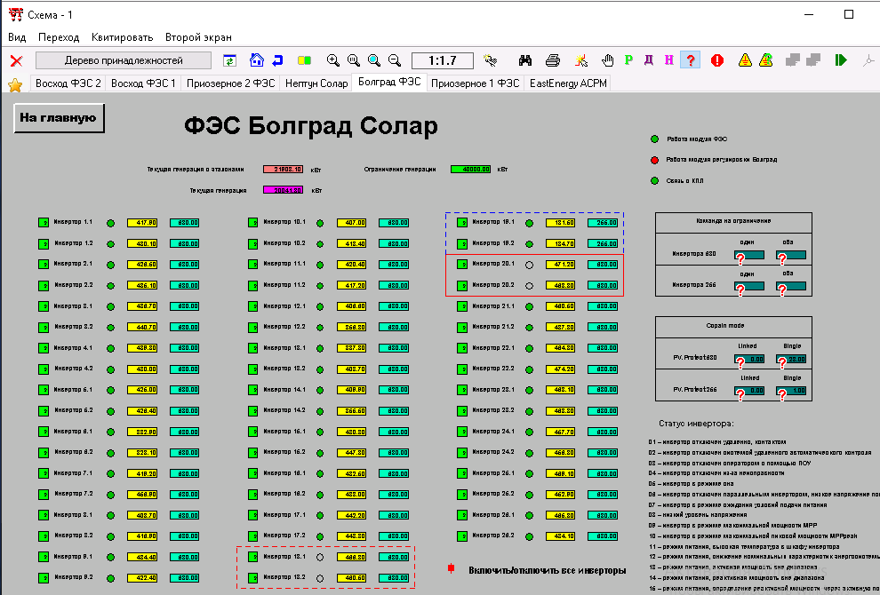
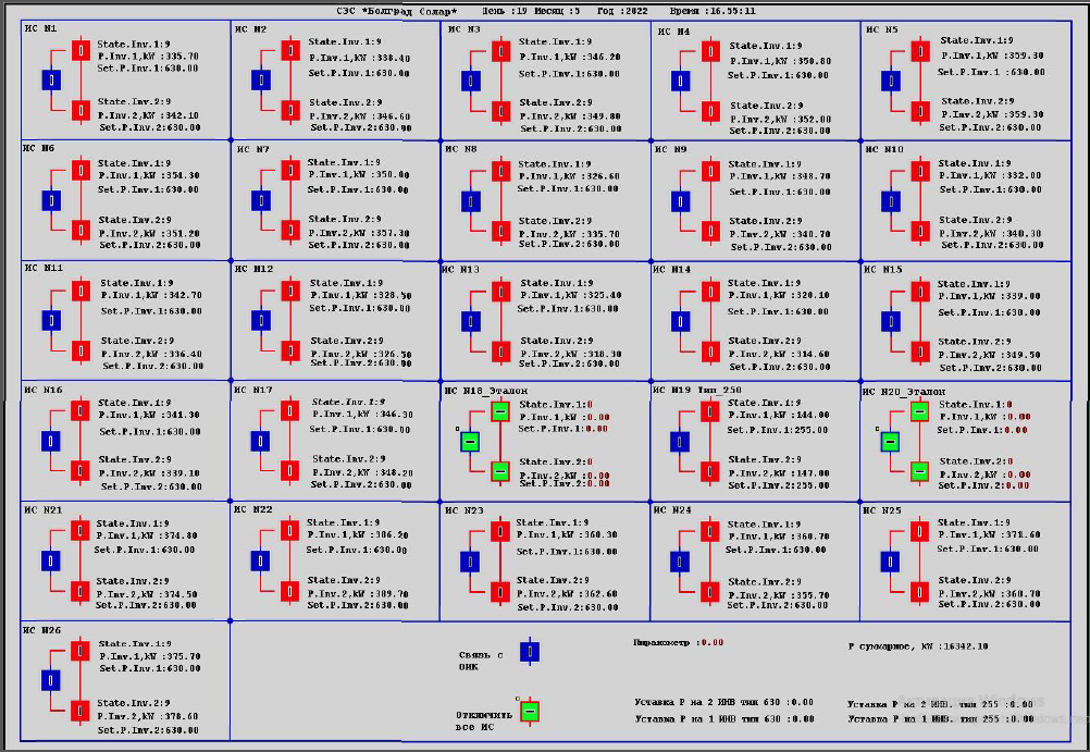
Screenshot of the control and management window on the monitor of the technological computer on duty at the SES communication node in the mode of operation through the Web SCADA interface.