Power supply systems
Uninterruptible Power Supply (UPS)
The quality of mains power supply and its problems
Power quality standards in general purpose power supply systems are assessed based on 10 indicators, the main of which are:
— voltage 380 V (for three-phase networks) and 220 V (for single-phase networks), permissible deviation ± 5%, maximum permissible ± 10%;
— Frequency 50 Hz, maximum permissible frequency deviation ± 0.4 Hz;
— the normal permissible value of the coefficient of nonlinear distortions is 6%, the maximum permissible value is 20%.
The main problems of network power supply include:
— complete loss of voltage in the network (accident in the network);
— long-term and short-term subsidence and voltage surges;
— High-voltage impulse interference;
— High-frequency noise;
— Frequency deviation beyond the permissible values.
The most common types of problems in large cities are long-term voltage sags, and in rural areas, power grid failures and high-voltage impulse disturbances caused by atmospheric electricity are added to them.
Critical Load (Critical Load)
The load, which is sensitive to faults in the power grid, risks equipment failure, disruption of the technological process or loss of important information. To prevent such cases, a UPS should be used to power such a load (file servers, workstations, personal computers, telecommunications and office equipment, etc.)
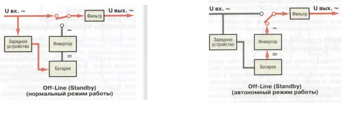
Backup type UPS (Off-Line or Standby)
Uninterruptible power supply, made according to the scheme with a switching device, which in normal operation ensures the connection of the load directly to the external power supply network, and in autonomous mode — transfers it to power from storage batteries. The advantage of a standby UPS is its simplicity and low cost, and the disadvantage is the non-zero switching time (~4 ms) to batteries and more intensive use of batteries, since the device switches to autonomous mode in case of any problems in the power grid. Standby UPSs, as a rule, have a small capacity and are used to ensure uninterrupted power supply of individual devices (personal computers, workstations, office equipment) in areas with good quality of the electrical network.
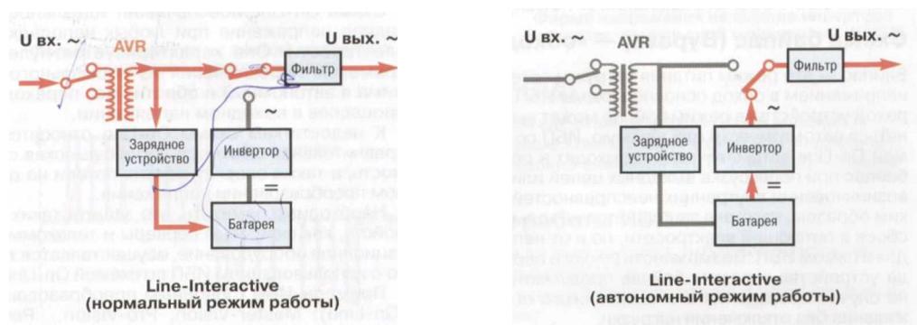
Linear-interactive UPS (IIPE-Interactive)
An uninterruptible power supply made according to the circuit with a switching device (Off-Line) and supplemented with an automatic voltage regulator (AVR) based on an autotransformer with switching windings (step stabilizer).
The main advantage of a linear-interactive UPS in comparison with a backup type source is that it is able to provide normal power supply to the load with increased or decreased voltage of the power grid (the most common type of malfunction in domestic power grids) without switching to autonomous mode. As a result, the battery life is extended.
The disadvantage of the linear-interactive scheme is the non-zero switching time (~4 ms) of the load to the battery power supply
In terms of efficiency, linear-interactive UPS occupy an intermediate position between simple and relatively cheap backup sources (Off-Line) and highly efficient, but expensive UPS with double energy conversion (Op-Line). As a rule, linear-interactive UPS are used to protect personal computers, monitors, workstations, nodes of local computer networks and other office equipment.
Examples of UPS with the Line-Interactive scheme.
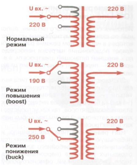
Automatic voltage regulator Automatic Voltage Regulator (AVR)
The automatic voltage regulator, built on the basis of an autotransformer with switching windings (see figures), is used in linear-interactive UPS for stepwise adjustment of the input voltage in the direction of its increase (reduced input voltage) or decrease (increased input voltage). The AVR extends the range of input voltages at which the UPS provides normal power to the load without going into stand-alone mode. The ranges of permissible changes in the input voltage can be 30% of the nominal value of 220 V.
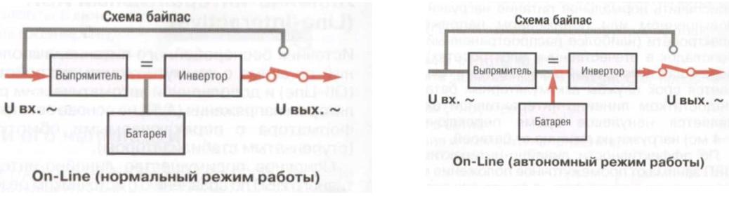
UPS with double voltage conversion (Op-Line)
The On-Line scheme assumes that the alternating mains voltage entering the UPS input is converted by a rectifier into a constant one, and then again into an alternating one with the help of an inverter. The battery, permanently connected between the rectifier and the inverter, powers the latter in emergency mode.
The Op-Line scheme provides the ideal output voltage in case of any problems in the power grid. It is characterized by zero switching time from normal mode to autonomous mode and back without transient processes in the output voltage
Disadvantages of the Op-Line scheme include its relative complexity, higher cost, as well as energy losses on double voltage conversion. Protection of such devices as file servers and telecommunication equipment is carried out only using UPS with Op-Line scheme.
Examples of UPS with double conversion (Op-Line)
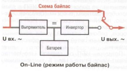
Bypass scheme - "bypass"
Bypass is a mode of feeding the load with mains voltage bypassing the main circuit of the UPS. Switching the device to bypass mode can be done automatically or manually. UPS with the Op-Line circuit automatically switch to bypass mode when output circuits are overloaded or in the event of internal malfunctions. Thus, the load is protected not only from failures in the power grid, but also from malfunctions in the UPS itself. The possibility of manually switching the device to the bypass mode is provided in case of its maintenance without disconnecting the load.
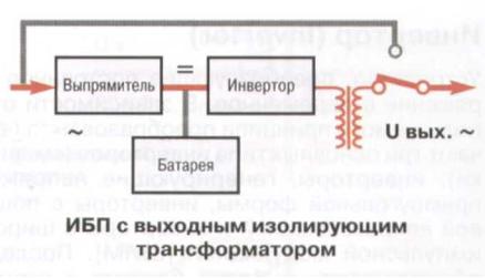
Classic UPS with an output isolating transformer
Inverters with an output isolating transformer are used in UPS of medium and large power with double voltage conversion (Op-Line) and intended for work with a wide range of loads.
Main advantages:
Ability to work with loads of any type with different power factors.
Stability of output parameters under both static and dynamic loading.
Allows you to implement any of the known power schemes (grounding systems) that supply: TN-C, TN-S, TN-C-S, TT and IT.
Galvanic isolation increases the interference immunity of the load both in the phases and on the neutral. The constant component of the output voltage is excluded.
The possibility of working with non-linear and pulsed loads due to a wide range of permissible cross-factor and load current KNI.
The possibility of feeding any single-phase and three-phase loads.
In connection with the use of an output transformer of the «delta-star» type, the output neutral is formed anew and all phase voltages are rigidly balanced.
The ability to work with unbalanced up to 100% three-phase loads of the «star» and «delta» type.
Main disadvantages:
Large dimensions and weight compared to transformerless ones.
Higher cost.
Transformerless UPS with On-Line circuit and high-frequency conversion
Transformerless inverters are used in UPS of medium and limited power (no more than 100 kVA — 200 kVA), built according to the ON-Line scheme with double voltage conversion. UPS of this type are mainly intended for protection of computer and other equipment with pulsed power sources.
The main advantages of transformerless circuits:
Small dimensions and weight.
Relatively high efficiency.
Limited list of loads (to protect computer equipment).
Below is the overload capacity and overall reliability of the UPS.
Not recommended for work with unstable and unbalanced load.
Input isolating transformer
The transformer is used to provide galvanic decoupling of the bypass circuit of its internal nodes and the AC220V input power network, as well as the transformation of the «delta» — «star» power system.
THD filter
A device installed in the input circuit of the UPS to reduce its influence on the form of current and voltage in the power supply network. Since the input node of any powerful UPS built according to the scheme with double conversion (On-Line) is a rectifier (a non-linear element that consumes a large impulse current), such a UPS becomes the cause of pollution of the power grid. The use of a THD filter allows you to significantly reduce such pollution. Powerful uninterruptible power supply systems should be equipped with filters that reduce the KNI of the input current to 5…10%.
Temperature compensation of battery charging current
Technology used by leading UPS manufacturers to extend battery life. As you know, sealed batteries are extremely sensitive to the charging current, the optimal value of which depends on the ambient temperature. The technology of temperature compensation of the charging current allows you to automatically adjust the battery charging mode in accordance with changes in external conditions and thus extend the life cycle of batteries several times.
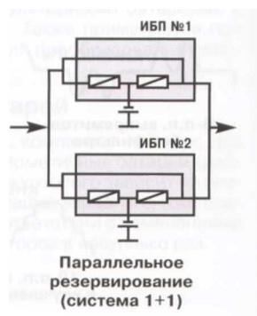
Parallel redundancy and system scaling
A technical solution aimed at increasing the reliability (hardware redundancy) of the device or increasing the total output power (scaling). It involves the parallel connection of two or more peer (equal power) UPSs at the input and output. The efficiency of such a system is ensured by a special phase synchronization scheme of the output voltages.
Examples of notation of parallel systems:
«1+1» is a system of two UPSs with 100% redundancy.
«2+1» is a system of three modules, one of which (any) is redundant (50% redundancy).
«N+2» is a system consisting of (N+2) modules, two of which (any) are redundant.
With hardware redundancy, the load is evenly distributed among all UPSs, and in case of failure of one of them, it is redistributed among healthy devices.
In the scheme with parallel redundancy, it is allowed to use separate batteries for each UPS, as well as a common set of batteries.
Main characteristics of UPS
Total Harmonic Distortions (TDH)
An indicator that characterizes the degree of difference in the form of a signal from a sinusoidal one. It is mainly used to measure input or output current shape distortions (Current THD). KNI is equal to the ratio of the sum of the powers of the higher harmonics of the signal to the power of its first harmonic. Typical KNI values:
0% — the waveform is a perfect sine wave.
3% — the shape of the signal is different from sinusoidal, but the distortions are not visible to the eye.
5% — the deviation of the waveform from the sinusoidal is visible to the eye on the oscillogram.
21% — for example, a trapezoidal or stepped signal.
43% — for example, a rectangular signal.
K-factor (K-Factor)
The K-factor, like the KNI of the current, characterizes the nonlinearity of the load, i.e. the amount of harmonic distortions that the consumer introduces into the power grid. In contrast to KND, when calculating the K-factor, higher current harmonics, which cause heat losses in power transformers, are more important. In fact, the K-factor is the coefficient of loss increase in the transformer due to load nonlinearity. There are specialized transformers that allow operation at increased K-factors of the load. They are more effective and safer and are recommended for use at responsible facilities. Examples: K = 1 (standard transformer); K=4…20 (improved transformers).
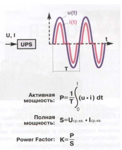
Active power
Useful power taken by the load from the UPS. It is calculated as the definite integral of the product of the instantaneous values of the input current and voltage, averaged over the signal period. Unit of measurement: W (watt).
Full power
Total power taking into account the active and reactive components, as well as the deviation of the current and voltage form from the harmonic one. It is calculated as the product of the rms values of the input current and voltage. Unit of measurement: VA (volt — ampere).
Power factor Roweg Fastog (PF)
A complex indicator that characterizes linear and nonlinear distortions of current and voltage in the power grid due to the influence of the load (for example, UPS). It is calculated as the ratio of the active power absorbed by the load to the total. Typical power factor values: 1 — Ideal value. 0.9 is a good indicator. 0.8 is a typical industrial load. 0.7 — computer load. 0.65 — two half-cycle rectifier. In the case of a linear load, the power factor is equal to the cosine of the shift angle between current and voltage and, depending on the nature of the load, can be capacitive or inductive in nature.
In the case of an active nonlinear load, the power factor is determined by the ratio of the power of the first harmonic of the current to the total active power consumed by the load.
It should be noted that the real industrial load is non-linear and is mainly capacitive in nature (РФ=0.8).
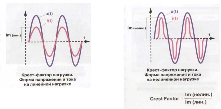
Cross load factor (Crest Factor, Cross Ratio)
An indicator that characterizes the UPS’s ability to supply a non-linear load that consumes pulsed (non-linear) current. It is defined as the ratio of the amplitude of the impulse current in a non-linear load lm (non-linear) to the amplitude of the current of the harmonic form lm (linear) at the equivalent power consumption (see figures). UPS of N-Power company are able to supply a non-linear load with a cross factor of up to 3.5:1.