MPDS-16-32


1. Purpose
1.1. The MPDS-16/32 module is designed to scan the states of up to 32 discrete signals
with verification of their authenticity with subsequent transmission, via a digital dedicated channel, to the collection controller.
2. Technical characteristics
2.1 The MPDS-16/32 provides scanning of the states of discrete signals on 32 input channels with subsequent transmission of authentic data via a dedicated digital channel, with a physical RS-485 interface, in the Modbus RTU data exchange protocol.
2.2 Serves one or two groups of 16 input channels, depending on the set
mode.
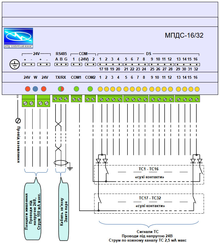
2.3 Has two return outputs for connecting the second wires from pairs of «dry» contacts
with 16 wires from each group.
2.4 All inputs are galvanically isolated from the digital electronic components of the module.
2.5 TC group polling cycle — 1 ms.
2.6 Polling voltage value 21 to 36 V DC.
1.7 Typical current value for each TC input channel is maximum 2.5 mA.
2.8 Contact chatter tracking in the range of 0…100 ms with a step of 1 ms.
2.9 Ability to set double TC switching time values in the range from 100 to 10,000 ms, discreteness 100 ms;
2.10 Processing up to 32 single-bit and 16 two-bit TC signals in various combinations.
2.11 Ability to programmatically invert the state of each TC;
2.12 Availability of a buffer for recording 32 TC «slices» (if there is a change in the state of at least
one of the TCs in one «slice») in case of loss of data exchange with the collection controller.
Filling principle – FІ-FO.
2.13 Data transmission to the collection controller via the RS485 physical interface according to the Modbus RTU data exchange protocol in “slave” mode. The exchange rate is from 9.6 to 56 kbaud
according to the standard range.
2.14 Service LED indicators and microswitches with the following functions:
— display of signal states at the inputs — 16 pcs (periodically display the states of the first and second groups of inputs), orange color;
— module operating status — blue;
— data reception/transmission process — two-color green/red
— presence of external power supply voltage 24 V — red;
— connection of switching voltage to one of the two groups of “dry contacts” — 2 LEDs
red;
— two microswitches, respectively, for setting the communication parameters «by default» and switching to the scanning mode of the first group of 16 channels, or two — 32 channels;
2.15 Service software for configuring the microcontroller of the module;
2.16 Plastic case with overall dimensions (LxWxH): 156 x 96 x 60 mm, weight —
0.15 kg. Mechanical protection — IP 44. Designed for mounting on a DIN rail.
,
3. Operating conditions
3.1 Supply voltage 21…36 V DC with consumption up to 60 mA.
3.2 Ambient temperature from minus 25 to 50 C° at relative humidity up to 85% without condensation, in rooms without increased danger.
3.3 Permissible breakdown voltage between the primary circuits of input signals and
other modules, 1.5 kV.
3.4 Electromagnetic compatibility according to:
— DSTU EN 61000-4-29: 2001 refers to category B;
— DSTU EN 55011: 2003 refers to class A, group 1.
3.5 Safety according to DSTU EN 60950-1: 2015:
— from electric shock refers to class III;
— fire resistance of the housing material refers to class 5VA.
4. Completeness
5.1 MPDS-16/32 is supplied as a stand-alone device with a set of appropriate parts
of external connectors and a Passport.
5.2 The module configuration service program is downloaded free of charge from the Manufacturer’s website www.energosv.org.ua.
5. Arrangement and description of operation
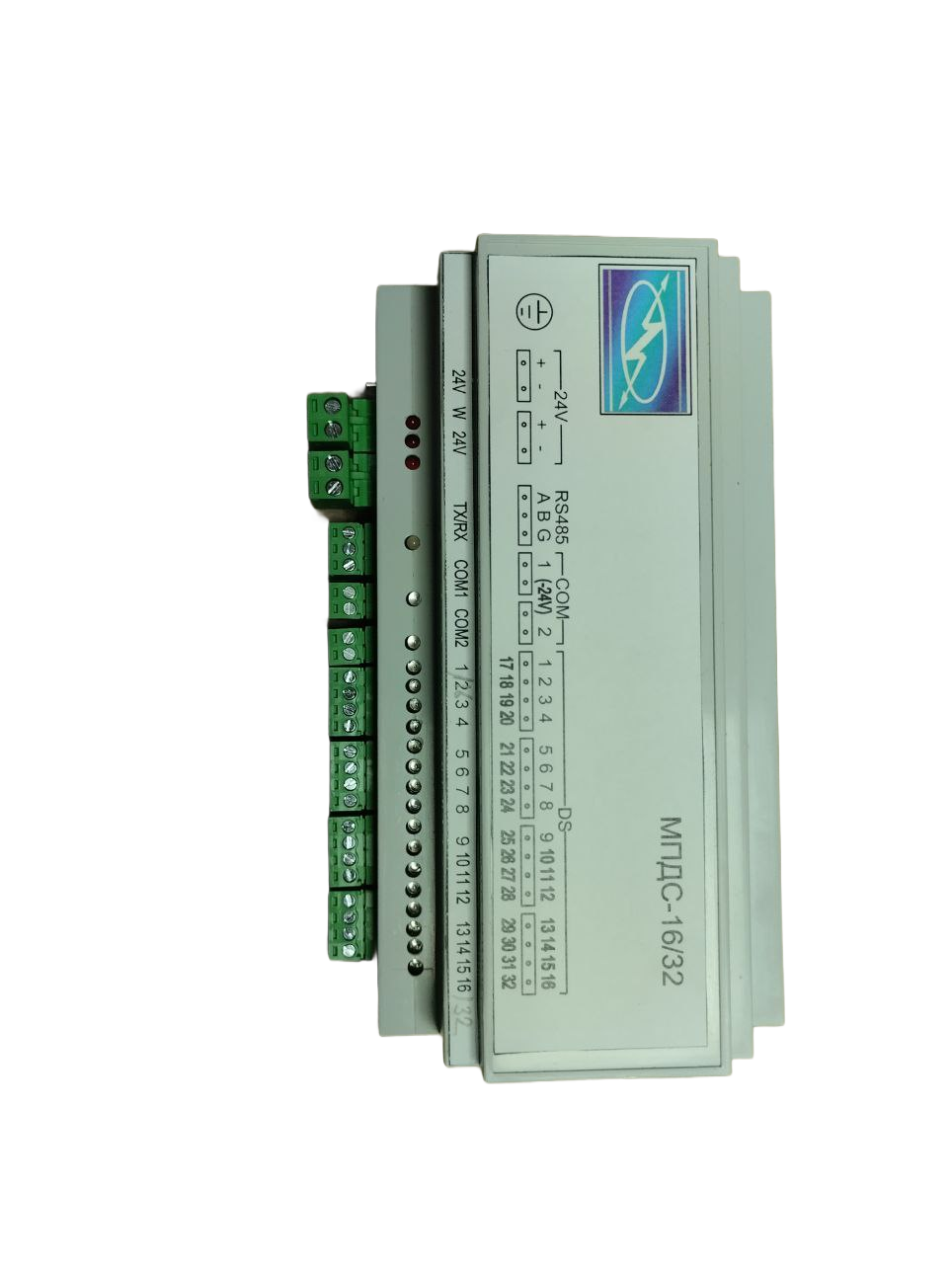
5.1 MPDS-16/32 is made in the form of a stand-alone plastic case, in which
a two-layer fiberglass printed circuit board with electronic components and switching elements mounted on it is installed.
For all external connections, connectors with «screw» wire fastening are used, and the information grounding of the common wire is using a knife terminal.
The cross-section of the wires for connection is no more than 1.5 mm².
The connectors are brought to the bottom of the case, and the service LED indicators are on the front panel.
The housing is fixed on a standard DIN rail with a width of 35 mm.
5.2 All tasks of the module are solved by the installed microcontroller with built-in Flash memory.
For galvanic isolation of the input channels, transistor optocouplers in the amount of
16 pcs.
Scanning of two groups of channels of 16 occurs alternately with a period of 0.5 ms.
Service LEDs display the status of the channels at the module inputs.
Connection of the second group of 16 channels is performed by external connection according to
the given figure 3.
Data transmission via the Modbus RTU exchange protocol («slave» mode) occurs via
the physical RS-485 interface.
The module is configured for operation at a specific facility using
a service program that is installed on a process computer. The computer is optionally connected to the MPDS-16/32 via the RS-485 port. After supplying external 24 V power, the module automatically switches to the operating mode of scanning input channels and issuing, upon request, verified states to the collection controller. 3 If changes in the states of input signals are recorded during the absence of requests, they are accumulated in a buffer with a depth of 32 addresses (operates in FI-FO mode) and are sequentially transmitted to the data collection controller when the exchange is resumed. The service indicator «WORK», which displays the operating state of the controller, in normal mode flashes at a frequency of 1 time per second, and in an emergency state (incorrect configuration error or lack of exchange with the collection controller) flashes at a double frequency. The MPDS-16/32 operates in a 24-hour maintenance-free mode and automatically restarts each time the power is turned on. The operating status is determined by the corresponding states of the service LED indicators.
Scheduled work is not provided
Made in Ukraine